Detection method
Diffuse, retro-reflective, through-beam, contrast, laser and other sensors behave differently on clear, dark, reflective or irregular packs. Select from real samples.
A photocell tells the coder when a product reaches the print point; an encoder tells it how fast the line is moving. Some applications need one, both or a different machine signal.
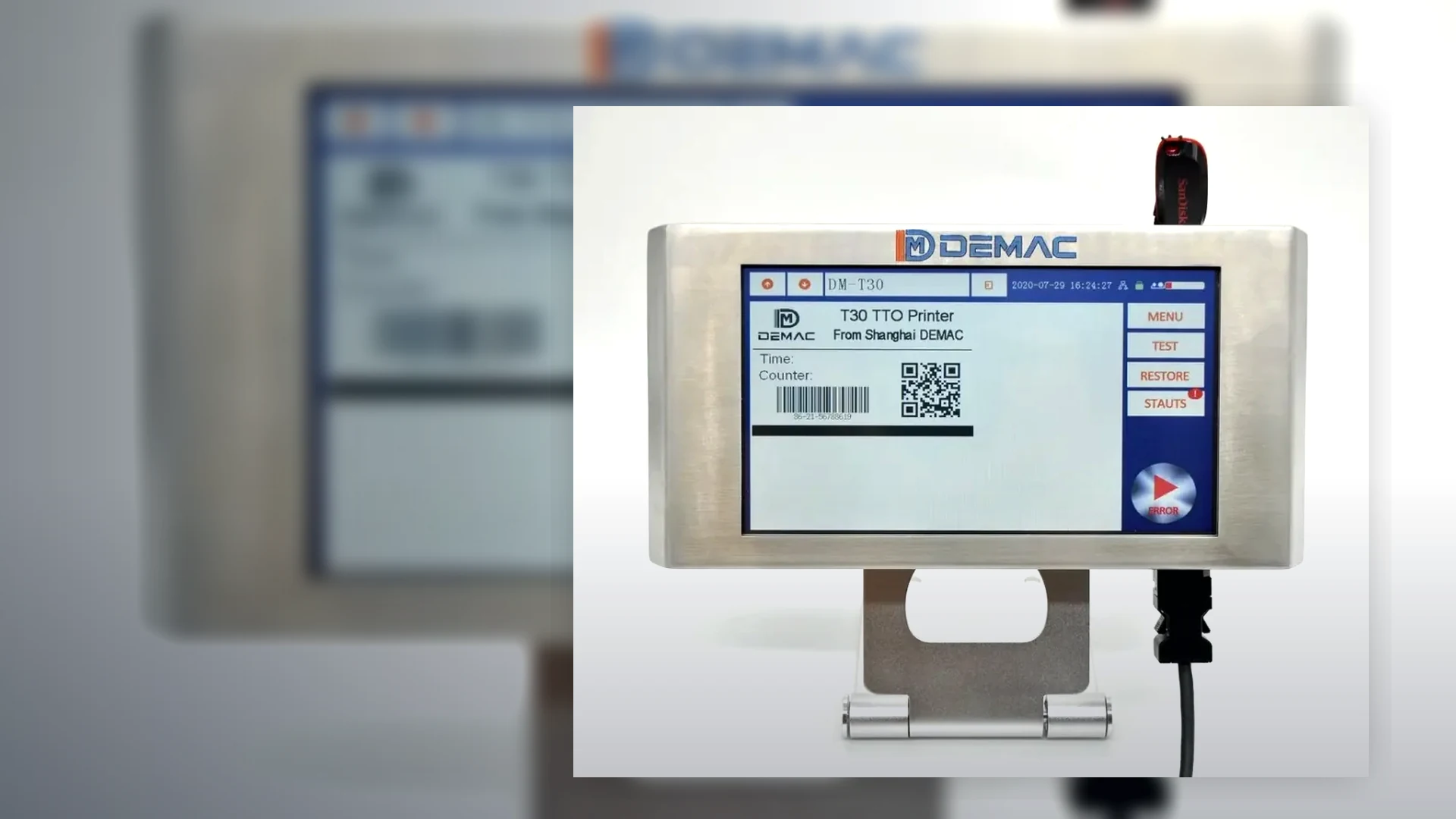
A product photocell or sensor creates the print trigger, while a shaft encoder measures movement so print timing or dot spacing can follow the conveyor. A fixed-speed line with stable products may not need an external encoder if the selected coder can use a proven internal speed setting. Variable-speed lines often need encoder feedback, but the final requirement is model- and application-specific.
The sensor and encoder are part of the coding process, not generic accessories. Their type, location, bracket, cable, input logic and failure response should be specified with the printer.
The sensor detects a repeatable feature of the pack and starts the programmed delay before printing. It must reliably distinguish products from gaps, conveyor parts, clear film, shiny reflections and background structures. The chosen trigger point should remain consistent across the approved product range.
Diffuse, retro-reflective, through-beam, contrast, laser and other sensors behave differently on clear, dark, reflective or irregular packs. Select from real samples.
Use a rigid protected bracket with access for cleaning and adjustment. Avoid a trigger feature that moves independently of the desired code position.
Closely spaced packs, bunching and variable pitch can create duplicate or missed triggers. Test minimum gap, maximum gap and stop/start conditions.
An encoder generates pulses related to conveyor movement. The coder can use those pulses to maintain character width, dot spacing or print delay as the line accelerates and slows. The wheel or drive connection must follow actual product movement without slip, bounce or loss of contact.
| Line condition | Likely trigger requirement | Likely speed input requirement |
|---|---|---|
| Fixed speed, evenly spaced products | Product sensor or reliable host-machine trigger. | Internal speed may be suitable if print quality is proven. |
| Variable conveyor speed | Product sensor or host-machine trigger. | Encoder or verified machine-speed signal is often required. |
| Intermittent indexing | Machine-position or print command synchronised to the dwell. | Depends on whether printing occurs while stationary or moving. |
| Continuous film web | Registration mark, machine signal or product event. | Encoder or host-machine motion data normally controls registration. |
| Multiple lanes | One or more lane-specific triggers, depending on pitch and independence. | Common or lane-specific movement reference, depending on mechanics. |
Both are commonly assessed when individual products must trigger printing while line speed varies. The sensor identifies the pack; the encoder tracks movement. They do not replace product guidance, because a correctly timed code can still be misplaced if the pack rotates or moves sideways.
Define whether the coder warns, inhibits printing, stops the line or allows production under a controlled fallback. The response should prevent silent missing, compressed or stretched codes and should be tested during commissioning.
Challenge minimum and maximum speed, acceleration, closely spaced products, gaps, product removal, line reversal where possible, stop/restart and every format. Record the approved sensor and encoder positions plus the message delay.
Provide line speed range, product pitch and a video of the coding point.
Lancing can specify the trigger and speed-reference route.