Inkjet coder support
Installation, mounting, troubleshooting and integration support for coding lines.
View details →Support for fitting inkjet coders to conveyors, fillers, cappers, labellers, case packers and existing production lines.
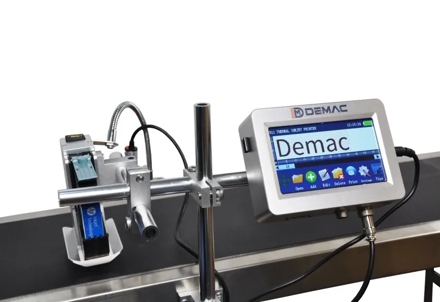
A good inkjet coder installation controls product position, print distance, trigger timing and operator access. Lancing can advise on the brackets, stands, sensors, encoders and surrounding handling needed to make the coding process stable.
| Installation checks | Print position, product control, coder access, sensor location, cable routes and guarding |
|---|---|
| Line equipment | Conveyors, label applicators, filling lines, cappers, case sealers and product handling |
| Data needed | Line speed, product dimensions, code content, available space, substrate and environment |
| Related options | Support, packaging line traceability and inkjet coding checklist |
Installation and support are strongest when the coder, product handling and operator workflow are treated as one process rather than separate items.
Send it with your enquiry so the coder type, bracket position, print head access and ink choice can be reviewed properly.
Compare related coder types, applications and specification guidance.
Installation, mounting, troubleshooting and integration support for coding lines.
View details →Coding, sensors, verification, rejects and data capture for production lines.
View details →Information to gather before requesting a coding machine recommendation.
View details →Send pack photos, code artwork, material, speed, code position and available line space. Lancing can then advise on the most suitable inkjet coding route.
Tell us what you need to code and where the coder has to fit on the line.
A coder can print an approved sample on a bench and still fail on the line if the product, sensor, printhead or data interfaces are not controlled. Installation planning should begin before equipment arrives.
| Interface | Installation information | Site acceptance check |
|---|---|---|
| Product handling | Speed, pitch, guides, stability, size range and code face | Position and quality across all formats and speeds |
| Mounting | Frame, adjustment, print gap, vibration, guarding and access | Repeatable changeover without collision or unsafe reach |
| Power and environment | Supply, isolation, earth, temperature, dust, washdown and ventilation | Installation matches published machine limits and site rules |
| Trigger and encoder | Sensor type, position, speed range and conveyor drive | One correct print per product through starts and speed changes |
| Controls and data | I/O, network, PLC, job selection and record source | Normal, fault, loss-of-data and recovery challenges |
| Inspection and reject | Reader, vision, reject window, confirmation and bin control | All defined good and bad test packs handled correctly |
Approve layout, utilities, mounting, cable routes, network, safety responsibilities and sample quantities. Complete site work that would prevent commissioning.
Record settings, approved messages, consumables, changeovers, alarms, cleaning, code samples and open actions. Use production operators where possible.
Confirm training, manuals, backups, spares, service contacts, acceptance records and responsibility for outstanding integration or validation work.
Send the line layout, code position and utilities for an installation-scope review.
Discuss coder installationMount them where the product is mechanically stable, the target surface is reachable and the sensor detects a feature that consistently relates to the code position. Keep brackets rigid, protected and accessible for safe cleaning and format adjustment.
Many coders do not require compressed air for basic printing, but some printhead protection, positive-air, cabinet, cleaning or application arrangements may. Confirm pressure, quality, flow and connection only from the exact proposed system.
Provide enough safe space to remove cartridges or fluid containers, clean the head, open doors, view alarms and adjust brackets without reaching through guards or over moving equipment. Model the task with the line stopped and isolated.
Test the final packs and messages at production speeds, including start/stop, changeover, sensor and encoder signals, job selection, faults, inspection, reject handling and recovery. Retain approved settings, samples and open actions.
Keep the machine identity, manuals, drawings, software or message backup, approved ink references, settings, passwords and permissions, training record, FAT/SAT results, maintenance tasks and support route. Link each format to its approved bracket, guide and message settings.
Close the installation with approved messages, model-specific consumable references, named operator tasks, backups and a record of every mounting and control interface. Those records make later servicing or replacement faster and lower risk.