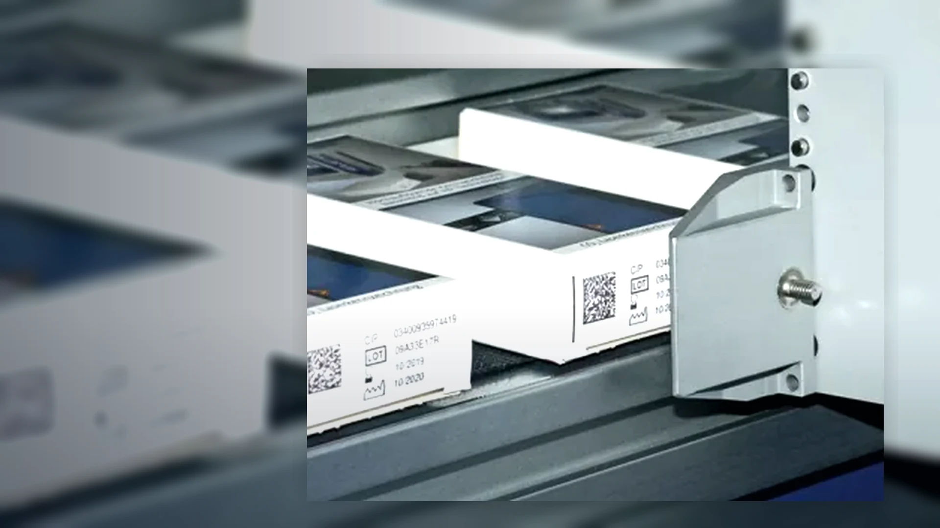
Continuous inkjet coders (CIJ)
Non-contact inkjet coders for fast moving bottles, cans, containers, flexible packs and irregular products where the code has to be applied while the line keeps moving.
View details →Traceability projects can combine inkjet printing with data handling, verification, inspection, reject control and operator procedures so every pack is coded correctly.
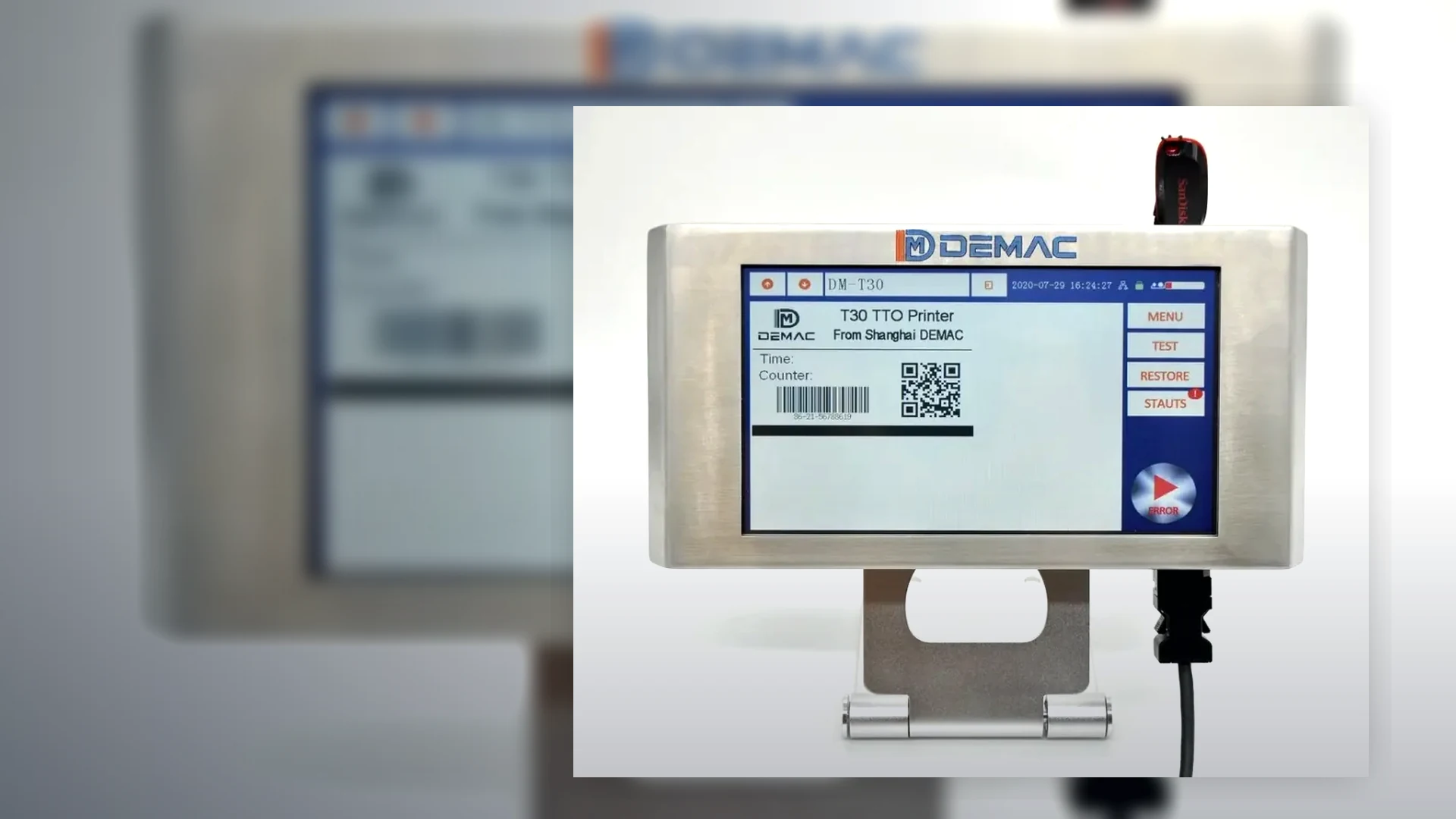
The coder must be matched to the product surface, line speed, orientation and the amount of variable data being printed. A practical trial is recommended where adhesion, dry time or barcode quality is important.
For high speed or curved products, start with continuous inkjet. For cartons, labels and flat surfaces requiring crisp codes, start with thermal inkjet. For outer cases, consider large character inkjet. For very low volumes, a handheld inkjet coder may be enough.
Send application detailsNon-contact inkjet coders for fast moving bottles, cans, containers, flexible packs and irregular products where the code has to be applied while the line keeps moving.
View details →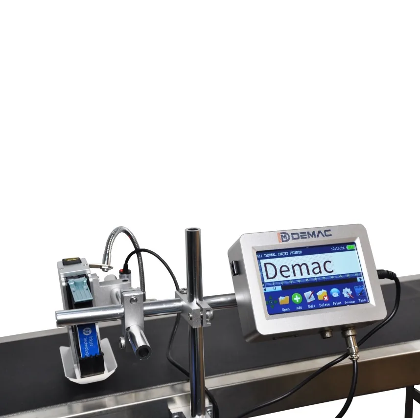
Clean cartridge-based inkjet printers for cartons, sleeves, labels, trays and porous or coated packaging where crisp text, QR codes and barcodes are required.
View details →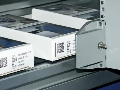
Industrial inkjet marking systems for outer cases, transit boxes and trays, replacing pre-printed cartons with flexible variable print.
View details →A printer creates a mark; a traceability system controls which data reaches which product, confirms the result and deals with exceptions. Define the complete sequence before choosing hardware or software.
Determine how the line knows which product and recipe is running: operator selection, barcode scan, PLC recipe, database order or ERP/MES instruction.
Define fixed and variable fields, date rules, lot format, serial source, check digits, user permissions and approval responsibility.
Use sensors, encoders or line tracking to associate one data record with one pack through printing, inspection and rejection.
Choose presence, OCR, barcode decoding or formal verification according to the risk. Define lighting, code position, sampling and acceptance.
Specify line stop or reject logic, reject confirmation, bin-full monitoring, reconciliation and restart rules after a fault.
State which records are stored, by whom, for how long and how they are linked to the production batch or order.
| Interface | Questions for the specification |
|---|---|
| PLC I/O | Ready, busy, print trigger, fault, low consumable, job selected, reject request and line-stop states. |
| Encoder and sensor | Speed range, resolution, product pitch, missing products, conveyor slip and mounting position. |
| Database / ERP / MES | Protocol, message structure, field validation, acknowledgement, buffering, sequence control and network ownership. |
| Vision or reader | Code type, field of view, lighting, expected grade or read rate, trigger and response time. |
| Reject system | Reject window, confirmation, fail-safe behaviour, bin security, full detection and reconciliation. |
| Audit data | Job, user, timestamp, printed record, inspection result, rejects, changes and backup. |
Define the applicable symbol and quality method with the customer or quality team. ISO/IEC 15416 is used for 1D label-based barcode grading; ISO/IEC 15415 applies to 2D symbols on labels; ISO/IEC TR 29158 addresses direct-part marks. A calibrated verifier is different from a production reader.
For GS1 symbols, confirm the correct identifier, data structure, size, quiet zone and application requirements. The code should be tested on the final pack in the intended orientation and lighting.
Challenge normal running and fault conditions: wrong recipe, no product, double product, speed change, unreadable code, missing code, network loss, printer fault, reject failure, power interruption and restart. Record the expected line response and evidence for each test.
Where the project requires formal validation, define the documentation and approval process before software configuration begins.
Identify who supplies and approves master data, date rules, serials and code layouts. The printer should not become an uncontrolled source of production data.
Agree addressing, ports, user access, backups, remote support and responsibility for updates. Keep production operation available when a non-essential external service is unavailable where the risk assessment permits.
Control revisions to messages, software, packaging artwork, code standards, readers and reject logic. Re-test affected functions after a change.
No. A reader decodes data under its operating conditions. A verifier uses controlled optics and calibration to measure defined print-quality parameters and produce a grade.
It can where the selected controller, software and protocol support the required workflow. Often a line PLC, middleware or coding-management system coordinates the connection.
The required behaviour must be defined: continue from an approved local job, stop safely, use a controlled buffer or prevent new production. The decision depends on traceability risk.
Use a controlled serial source, acknowledgement, product tracking, inspection and reconciliation. Recovery after stops or rejected products must be part of the design.
That depends on the product, customer and risk. Some applications use 100% inline checks; others use sampled inspection or offline verification. Define the requirement before selecting equipment.
Provide the data source, code format, line sequence and failure responses for an integration review.
Discuss coding and traceability integrationA traceability system is only controlled when normal production and exception states are both specified. The line should know which record belongs to each product, whether the mark was applied, what inspection found and what happened to a failed item.
| Event | Detection and evidence | Response to define |
|---|---|---|
| Wrong or unapproved job selected | Recipe ID, operator login, expected product reference and comparison result. | Prevent start, require authorised confirmation or stop the line before product enters the coding zone. |
| Required data missing or invalid | Missing field, invalid format, duplicate serial or source-system error with timestamp. | Hold the job, reject the affected product or stop according to the agreed criticality; never silently print a default value. |
| Product detected but print not confirmed | Sensor event, coder busy or ready state, print trigger and controller acknowledgement. | Track the product to inspection or reject and create a visible fault for the operator. |
| Code absent or unreadable | Vision or reader result linked to product position and image or result record where required. | Reject, stop or divert the product; define retry rules and prevent rejected product re-entering unnoticed. |
| Reject not proven | Reject command, confirmation sensor, bin level or reject-station status. | Stop the line or enter a controlled fault state when the failed item cannot be accounted for. |
| Network or database connection lost | Connection state, last accepted record, queue depth and local-buffer status. | Define whether controlled buffered production is allowed, how duplicate or skipped records are prevented and how reconciliation occurs. |
| Power cycle or emergency stop | Last tracked product, current serial or batch, queued records and line position. | Define restart clearance, record recovery and treatment of products between the coder, inspection and reject points. |
Assign ownership for product codes, date rules, batch formats, templates and barcode structures. Use approval and revision control so a valid source record cannot be combined with an obsolete print layout.
Agree the authoritative clock, time zone, shift boundaries and date rollover. Record the line, coder, job, product and operator identities needed to understand an event later.
Define what must be stored, for how long, in which system and how it is searched or exported. A record should be linked to the physical production event rather than exist as an unverified print command.
Name who supplies and validates the master data, network, PLC changes, vision equipment, reject mechanics, safety changes, software licences, backup and production reporting. Record the protocol, field mapping and version at handover.
For broader coordination of filling, capping, labelling, conveying, inspection and end-of-line equipment, use the packaging-line integration resource. Inkjet-specific selection remains on this site.
Provide the data fields, line sequence and required failure behaviour.
Lancing can review the inkjet coder interfaces against the wider traceability scope.
One controlled system should own each approved data field, with defined responsibility for creation, validation, transfer and change. The coder should not silently substitute local data when an ERP, MES, PLC or recipe is the approved source. Document the fallback and recovery route.
The response should prevent unmarked or uncontrolled packs from continuing unnoticed. Depending on risk, the line may inhibit infeed, stop, alarm or divert product. Test low consumable, no job, communications loss, printer fault and not-ready states.
Reject confirmation uses a sensor or equivalent evidence to show that the targeted product left the accepted-product path. It should also detect a full reject bin, failed actuator or missing confirmation and respond according to the agreed risk control.
Keep the time, product, job, expected data, printed result, alarm, line state, rejected range, corrective action and release decision. Records should allow the affected production window to be identified without relying on memory.
Separate authorised job creation from routine job selection, protect date rules and variable fields, and record who changed what and when where the risk requires it. Challenge access, wrong-job selection and restart recovery during acceptance testing.
See the question library and the sensor and encoder guide.
Discuss coding traceabilityCurrent Lancing reference models show several levels of integration. The final controls scope must identify the data owner, trigger, speed input, line enable, fault response, inspection and reject confirmation.
| Model | Reference interface | Traceability boundary to define |
|---|---|---|
| LU-TIP15 | Product sensor, encoder, guarded head mount and PLC enable/fault interface. | Message source, barcode/QR configuration, fault state and line response. |
| LU-IIP600-B | Photoelectric trigger, encoder speed compensation and stored touchscreen template. | Authorised data change, print delay, first-off check and missing-code response. |
| LU-IIP550 | Touchscreen recipe selection with configurable single or multiple heads. | Head order, combined message, external data fields, inspection and recovery if one head is unavailable. |
Provide an interface list showing every signal, data field, alarm and recovery state expected from the coding point.
Review the traceability interface